mardi 28 août 2018

Dos, Avec un PING -a recupérer le nom de machine


for /f "tokens=1-6 delims= " %a in ('ping -a 192.168.1.15^|find "ping"') do echo %f


Sur la commande PING -a sur l'IP 192.168.1.15
trouver la ligne comprenant "PING
puis rechercher les 6 premiers éléments qui sont séparé par des espaces
et afficher le 6ème élément (soit F la 6ème lettre)

vendredi 24 août 2018

Arduino Episode 6 : Module NFC PN532


(Arduino Uno)
Bonjour,

J'ai acquis depuis un moment maintenant un module NFC (sans marque ni modèle) qui pourrait s'aparenter à un PN532 de chez IteadStudio.
Voici la bête :

Au delà de ses 2 rangées de PIN, on peut trouver 2 curseurs (à droite) Indiquant SET0 et SET1 position LOW ou High.
En retournant la carte on trouve le tableau suivant:


SET0SET1
LOWLOWUART
LOWHIGHSPI
HIGHLOWIIC

1°) Les Curseurs
Déjà nous allons utiliser le protocole SPI (je n'ai rien inventé, j'ai juste repris  les infos d'autres personnes
Donc SET0 = LOW et SET1 = HIGH

2°) Branchements
Laissons la grande rangée de PIN et focalisons nous sur la petite:
NFC > Arduino
SCK > 13
MI > 12
MO/SDA/TX > 11
NSS/SCL/RX >10
IRQ

RST
GND > GND
5V > 5V


3°) Le Code
Nous allons utiliser le code d'ADAFRUIT et le modifier légèrement
Dans Arduino IDE, Croquis, Inclure une bibliothèque, Gérer les Bibliothèques, chercher PN532 de Adafruit.
Ouvrir l'exemple : Fichier, exemple, Adafruit PN532, ISO14443a_uid

Changez les ports ainsi: (pour correspondre au branchement)
// If using the breakout with SPI, define the pins for SPI communication.
#define PN532_SCK  (13)
#define PN532_MOSI (12)
#define PN532_SS   (10)
#define PN532_MISO (11)

Soit au final:
/**************************************************************************/
/*!
@file iso14443a_uid.pde
@author Adafruit Industries
@license BSD (see license.txt)

This example will attempt to connect to an ISO14443A
card or tag and retrieve some basic information about it
that can be used to determine what type of card it is.

Note that you need the baud rate to be 115200 because we need to print
out the data and read from the card at the same time!

This is an example sketch for the Adafruit PN532 NFC/RFID breakout boards
This library works with the Adafruit NFC breakout
----> https://www.adafruit.com/products/364

Check out the links above for our tutorials and wiring diagrams
These chips use SPI or I2C to communicate.

Adafruit invests time and resources providing this open source code,
please support Adafruit and open-source hardware by purchasing
products from Adafruit!

*/
/**************************************************************************/
#include <Wire.h>
#include <SPI.h>
#include <Adafruit_PN532.h>

// If using the breakout with SPI, define the pins for SPI communication.
#define PN532_SCK (13)
#define PN532_MOSI (12)
#define PN532_SS (10)
#define PN532_MISO (11)

// If using the breakout or shield with I2C, define just the pins connected
// to the IRQ and reset lines. Use the values below (2, 3) for the shield!
#define PN532_IRQ (2)
#define PN532_RESET (3) // Not connected by default on the NFC Shield

// Uncomment just _one_ line below depending on how your breakout or shield
// is connected to the Arduino:

// Use this line for a breakout with a SPI connection:
//Adafruit_PN532 nfc(PN532_SCK, PN532_MISO, PN532_MOSI, PN532_SS);

// Use this line for a breakout with a hardware SPI connection. Note that
// the PN532 SCK, MOSI, and MISO pins need to be connected to the Arduino's
// hardware SPI SCK, MOSI, and MISO pins. On an Arduino Uno these are
// SCK = 13, MOSI = 11, MISO = 12. The SS line can be any digital IO pin.
Adafruit_PN532 nfc(PN532_SS);

// Or use this line for a breakout or shield with an I2C connection:
//Adafruit_PN532 nfc(PN532_IRQ, PN532_RESET);

void setup(void) {
Serial.begin(115200);
Serial.println("Hello!");

nfc.begin();

uint32_t versiondata = nfc.getFirmwareVersion();
if (! versiondata) {
Serial.print("Didn't find PN53x board");
while (1); // halt
}

// Got ok data, print it out!
Serial.print("Found chip PN5"); Serial.println((versiondata>>24) & 0xFF, HEX);
Serial.print("Firmware ver. "); Serial.print((versiondata>>16) & 0xFF, DEC);
Serial.print('.'); Serial.println((versiondata>>8) & 0xFF, DEC);

// Set the max number of retry attempts to read from a card
// This prevents us from waiting forever for a card, which is
// the default behaviour of the PN532.
nfc.setPassiveActivationRetries(0xFF);

// configure board to read RFID tags
nfc.SAMConfig();

Serial.println("Waiting for an ISO14443A card");
}

void loop(void) {
boolean success;
uint8_t uid[] = { 0, 0, 0, 0, 0, 0, 0 }; // Buffer to store the returned UID
uint8_t uidLength; // Length of the UID (4 or 7 bytes depending on ISO14443A card type)

// Wait for an ISO14443A type cards (Mifare, etc.). When one is found
// 'uid' will be populated with the UID, and uidLength will indicate
// if the uid is 4 bytes (Mifare Classic) or 7 bytes (Mifare Ultralight)
success = nfc.readPassiveTargetID(PN532_MIFARE_ISO14443A, &uid[0], &uidLength);

if (success) {
Serial.println("Found a card!");
Serial.print("UID Length: ");Serial.print(uidLength, DEC);Serial.println(" bytes");
Serial.print("UID Value: ");
for (uint8_t i=0; i < uidLength; i++)
{
Serial.print(" 0x");Serial.print(uid[i], HEX);
}
Serial.println("");
// Wait 1 second before continuing
delay(1000);
}
else
{
// PN532 probably timed out waiting for a card
Serial.println("Timed out waiting for a card");
}
}
4°)Moniteur Série:
Au début j'avais le message:
“Didn't find PN53x board
en fait, j'avais suivi un vidéo youtube (voir lien) qui préconisait de commenter la ligne
Adafruit_PN532 nfc(PN532_SCK, PN532_MISO, PN532_MOSI, PN532_SS);
et de décommenter la ligne
//Adafruit_PN532 nfc(PN532_IRQ, PN532_RESET);

Ce n'était pas une bonne solution.

[Edit 31/12/18] Sur du NANO : Voici ce que j'ai commenté et décommenté :

Commenté: //Adafruit_PN532 nfc(PN532_SCK, PN532_MISO, PN532_MOSI, PN532_SS);
Décommenté: Adafruit_PN532 nfc(PN532_SS);
Commenté car pas I2C ://Adafruit_PN532 nfc(PN532_IRQ, PN532_RESET);

En passant un badge NFC:
Hello!
Found chip PN532
Firmware ver. 1.6
Waiting for an ISO14443A card
Found a card!
UID Length: 4 bytes
UID Value:  0xDB 0xAD 0xC9 0x50


Et Voilà...

5°) Sources
https://www.youtube.com/watch?v=TvKOhcHH32M
http://lantaukwcounter.blogspot.com/2015/11/reading-octopus-card-ids-felica-with.html
https://forum.snootlab.com/viewtopic.php?f=45&t=1091
https://arduino.stackexchange.com/questions/49616/problem-didnt-find-pn53x-board-in-arduino-uno-e-card-reader


mercredi 22 août 2018

Arduino Episode 5 : RFID et RC522


Aujourd'hui on reprend l'Arduino (Uno) ainsi que le module RFID-RC522 (13,56 Mhz comme le NFC) et on mélange le tout.
(Plus d'informations sur le RFID ici :rfid-la-technologie)


La carte se connecte en 3.3V donc, pour un arduino Nano, il va falloir faire attention ( resistance ou Pin particulier ???)


Je reprend les informations et y ajoute mes problèmes.

1°)Branchement , on va commencer par le code car avec le module, l'arduino ne répondait plus
#include <SPI.h>
#include <RFID.h>

RFID monModuleRFID(10,9);

int UID[5];

void setup()
{
Serial.begin(9600);
SPI.begin();
monModuleRFID.init();

}

void loop()
{
if (monModuleRFID.isCard()) {
if (monModuleRFID.readCardSerial()) {
Serial.print("L'UID est: ");
for(int i=0;i<=4;i++)
{
UID[i]=monModuleRFID.serNum[i];
Serial.print(UID[i],DEC);
Serial.print(".");
}
Serial.println("");
}
monModuleRFID.halt();
}
delay(1);
}
2°) Branchement UNO
RFID-RC522 <> Arduino
SDA <> 10
SCK<> 13
MOSI<> 11
MISO<> 12
IRQ<> (non branché)
GND<> GND
RST<> 9
3.3V<> 3.3V

3°) Dans la console "Moniteur Série"
On obtient des lignes de ce type :
L'UID est: 241.146.62.181.81.

Pour les branchements sur un arduino NANO:
https://www.memorandum.ovh/tuto-arduino-utiliser-un-module-rfid/
https://ouiaremakers.com/posts/tutoriel-diy-arduino-rfid-rc522
  Bugs:
[edit 02/01/19]
J'ai testé sur un NANO, et aucun affichage. défait les branchements, refait, testé sur un autre NANO idem, rien ne s'affichait dans la console. idem avec plusieurs codes et sources différentes.
Zut mon module est grillé... attend... ma vitesse d'affichage ne serait-elle pas trop élevé ?
11500 au lieu de 9600, et rien ne s'affiche, je change en 9600 et tout est OK :)

vendredi 17 août 2018

NodeMCU Episode 1 : Début et LCD

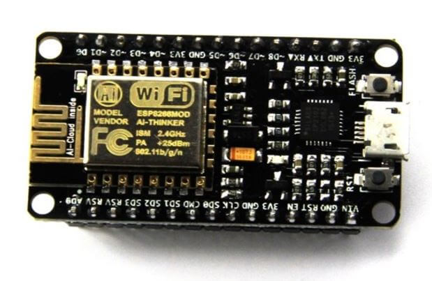
Le nodeMCU est un microcontroleur au même titre que l'arduino mais doté d'une puce ESP8266 ajoutant la possibilité d'utiliser les réseaux Wifi.


Raspberry Pi: MicroOrdinateur
Arduino: Carte de microControleur
Atmel: Puce microcontroleur (présent dans l'arduino)
ESP8266 :Puce Wifi
ESP32 : Nouvelle Génération de l'ESP8266
NodeMCU: MicroControleur avec un ESP8266

Comme l'arduino, il suffit de brancher en microUSB sur un PC et d'envoyer son code avec le logiciel ARDUINO IDE.
Arduino IDE ne comprend pas la librairie pour ce matériel, une petite installation est nécessaire.

Fichier / Préférence / URL de gestionnaire de carte supplémentaire : (ajouter ce lien)
http://arduino.esp8266.com/versions/2.4.2/package_esp8266com_index.json
Puis, Outils / Type de Carte / Gestionnaire de carte / rechercher : ESP8266 et l'installer
Encore Outils / Type de Carte : NodeMCU 0.9 (ESP 12 Module)
Encore Outils / Upload Speed: 115200


1°)Branchement
LCD > NodeMCU
GND > GND
VCC > VU
SDA > D2
SCL > D1

2°)Code :Ajouter et téléverser le code 

//YWROBOT
//Compatible with the Arduino IDE 1.0
//Library version:1.1
#include <wire.h>
#include <liquidcrystal_i2c.h>

LiquidCrystal_I2C lcd(0x27,20,4);  // set the LCD address to 0x27 for a 16 chars and 2 line display

void setup()
{
  lcd.init();                      // initialize the lcd
  lcd.init();
  // Print a message to the LCD.
  lcd.backlight();
  lcd.setCursor(3,0);
  lcd.print("Hello, world!");
  lcd.setCursor(2,1);
  lcd.print("Ywrobot Arduino!");
   lcd.setCursor(0,2);
  lcd.print("Arduino LCM IIC 2004");
   lcd.setCursor(2,3);
  lcd.print("Power By Ec-yuan!");
}

void loop()
{
}


Fritzing: découverte

Voici un petit article pour apprendre à utiliser FRITZING: 


Fritzing est un outil OpenSource et gratuit, permettant de réaliser des montages électroniques à des fin de présentation.

L'outil est simple d'utilisation et pratique.
http://fritzing.org/home/

Téléchargez, décompressez et Utilisez-le.

Pour les présentation, restez sur l'onglet Platine d'essai

Sur le côté droit, se trouve les composant disponibles. Vous pouvez en télécharger d'autres (github ou autres) et les ajouter en faisant fichier, ouvrir.
Ils iront s'ajouter automatiquement dans la bibliothèque myPart

Vous pouvez reliez les composants directement, et ajouter des coudes pour que ce soit plus joli.
Vous pouvez également changer la couleur du câble , ou détail des composant, toujours dans la fenêtre de droite.

Un exemple en vidéo :https://www.youtube.com/watch?v=g5PIiQTjel8

Alternative:
Simulateur : NG SPICE
http://ngspice.sourceforge.net/

Arduino Episode 4 : LCD + 433MHz


(Arduino Nano)
Au même titre que mon raspberry, j'ai voulu utiliser mon Arduino pour afficher des informations sur mon écran LCD:

1°) Branchement :
GND sur GND
VCC sur 5V
SDA sur A4
SCL sur A5

Branchement du module 433Mhz
VCC sur 5V
GND sur GND
DATA sur D2

1BIS°) Interessant:
Il existe une fonction sur pour allumer l'écran:

lcd.backlight();
et une pour le mettre en veille.
lcd.noBacklight();

2°) Librairie sur l'outil ARDUINO IDE
Croquis / Inclure une Bibliothèque / Ajouter la bibliothèque ZIP :
http://downloads.arduino.cc/libraries/github.com/marcoschwartz/LiquidCrystal_I2C-1.1.2.zip

3°) Inclure et téléverser le code :

#include <liquidcrystal_i2c.h>


RCSwitch mySwitch = RCSwitch();
LiquidCrystal_I2C lcd(0x27, 20, 4);


void setup() {
lcd.init();
}

void loop() {
lcd.backlight();

lcd.setCursor(0,0);
lcd.print(" Test Ecran LCD");

lcd.setCursor(0,1);
lcd.print(" sur");

lcd.setCursor(0,2);
lcd.print("Arduino");

lcd.setCursor(0,3);
lcd.print("Nano");
}


Et si on rajoute un module 433 voici le code

#include <LiquidCrystal_I2C.h>
#include <RCSwitch.h>
#include <Wire.h>


RCSwitch mySwitch = RCSwitch();
LiquidCrystal_I2C lcd(0x27, 20, 4);

void setup() {
Serial.begin(9600);
mySwitch.enableReceive(0); // Receiver on interrupt 0 => that is pin #2
lcd.init();
}

void loop() {
lcd.backlight();
if (mySwitch.available()) {
output(mySwitch.getReceivedValue(), mySwitch.getReceivedBitlength(), mySwitch.getReceivedDelay(), mySwitch.getReceivedRawdata(),mySwitch.getReceivedProtocol());


lcd.setCursor(0,0);
lcd.print("value: ");
lcd.setCursor(7,0);
lcd.print(mySwitch.getReceivedValue());

lcd.setCursor(0,1);
lcd.print("delai: ");
lcd.setCursor(7,1);
lcd.print(mySwitch.getReceivedDelay());

lcd.setCursor(0,2);
lcd.print("longu:");
lcd.setCursor(7,2);
lcd.print(mySwitch.getReceivedBitlength());

lcd.setCursor(0,3);
lcd.print("Proto: ");
lcd.setCursor(7,3);
lcd.print(mySwitch.getReceivedProtocol());
mySwitch.resetAvailable();
}
}


et la fonction OutPut, comprise dans les exemples

static const char* bin2tristate(const char* bin);
static char * dec2binWzerofill(unsigned long Dec, unsigned int bitLength);

void output(unsigned long decimal, unsigned int length, unsigned int delay, unsigned int* raw, unsigned int protocol) {

if (decimal == 0) {
Serial.print("Unknown encoding.");
} else {
const char* b = dec2binWzerofill(decimal, length);
Serial.print("Decimal: ");
Serial.print(decimal);
Serial.print(" (");
Serial.print( length );
Serial.print("Bit) Binary: ");
Serial.print( b );
Serial.print(" Tri-State: ");
Serial.print( bin2tristate( b) );
Serial.print(" PulseLength: ");
Serial.print(delay);
Serial.print(" microseconds");
Serial.print(" Protocol: ");
Serial.println(protocol);
}

Serial.print("Raw data: ");
for (unsigned int i=0; i<= length*2; i++) {
Serial.print(raw[i]);
Serial.print(",");
}
Serial.println();
Serial.println();
}

static const char* bin2tristate(const char* bin) {
static char returnValue[50];
int pos = 0;
int pos2 = 0;
while (bin[pos]!='\0' && bin[pos+1]!='\0') {
if (bin[pos]=='0' && bin[pos+1]=='0') {
returnValue[pos2] = '0';
} else if (bin[pos]=='1' && bin[pos+1]=='1') {
returnValue[pos2] = '1';
} else if (bin[pos]=='0' && bin[pos+1]=='1') {
returnValue[pos2] = 'F';
} else {
return "not applicable";
}
pos = pos+2;
pos2++;
}
returnValue[pos2] = '\0';
return returnValue;
}

static char * dec2binWzerofill(unsigned long Dec, unsigned int bitLength) {
static char bin[64];
unsigned int i=0;

while (Dec > 0) {
bin[32+i++] = ((Dec & 1) > 0) ? '1' : '0';
Dec = Dec >> 1;
}

for (unsigned int j = 0; j< bitLength; j++) {
if (j >= bitLength - i) {
bin[j] = bin[ 31 + i - (j - (bitLength - i)) ];
} else {
bin[j] = '0';
}
}
bin[bitLength] = '\0';

return bin;
}

mardi 7 août 2018

Arduino : Episode 3: les erreurs / syntax error


(Arduino Uno/Nano)
Voici un petit medley des erreurs arduino que j'ai pu rencontrer (et resoudre)

1°)
arduino avrdude: stk500_recv(): programmer is not responding
(Lors du téléversement / Windows 10 / HP X360 G2)

>> le driver USB2.0-Serial n'était pas installé dans le gestionnaire de périphérique, une recherche du driver sur internet à résolu le problème. (USB-SERIAL CH340)

>>Débrancher les modules sur l'arduino, celui-ci doit être "nu" lorsque le téléversement est effectué

>> Outils/Processeur/Atmega328P (OldBootLoader)

2°)
avrdude: stk500_recv(): programmer is not responding
avrdude: stk500_getsync() attempt 10 of 10: not in sync: resp=0x68
Problème de téléversement vers la carte. Voir http://www.arduino.cc/en/Guide/Troubleshooting#upload pour suggestions.
>> débranche, rebranche l'USB de l'arduino

3°)
ATTENTION : La catégorie 'Device Control, Signal Input/Output' dans la bibliothèque rc-switch n'est pas valide. Définition sur : 'Uncategorized'
(Lors de la compilation / Windows 10 / HP X360 G2)
Il s'agit d'une alerte non bloquante dans la bibliothèque RC-SWITCH qui gère les modules 433mHz

4°)Information dans la console incompréhensible :
ex:
⸮⸮H⸮L⸮⸮
⸮⸮⸮ʈ⸮!)ļ2y⸮)!⸮!. ⸮ ⸮!)x⸮
>> Changez en bas le bitrate: exemple de 9600 baud à 115200

5°) Code non executé
J'ai 2 ESP8266 ou ESP32 et sur mon Lolin, le code s'execute bien sur le Noname il ne fonctionne pas du tout.
Après de nombreux tests, j'ai trouvé qu'un module (le lolin ) fonctionne avec :NodeMCU 1.0 (ESP-12E Module) et l'autre avec (le noname) NodeMCU 0.9 (ESP-12 Module).

6°) Chargement de code:
error: espcomm_upload_mem failed
Le câble USB est mal branché à l'ordinateur, aucun PORT COM n'est détécté, donc aucun téléversement.
>>Débrancher rebrancher le câble USB

Dans la console, en utilisant le bouton reset, j'ai le code ressemblant à :
;ld??|?$?|OO.......
à 115200 baud
en passant à  74880,le code devient
ets Jan  8 2013,rst cause:2, boot mode:(3,6)

J'ai eu beau reflasher à diffent bitrate, avec different firmware, deployer different code, rien n'y fait.
Du coup je suis resté sur mon 115200 partout, flashé avec nodemcu_integer_0.9.6-dev_20150704.bin, changé le type de carte dans Arduino IDE. et c'est passé.
Le premier code de la carte n'est pas visible mais le code passe ensuite, il faut patienter.
Bref, il faut changer le type de carte

7°) Fatal Exception
Fatal exception (0):  epc1=0x40100002, epc2=0x00000000, epc3=0x00000000, excvaddr=0x00000000, depc=0x00000000
Voici un message trouvé dans la console en vitesse 74880
Bref, j'ai branché le 5V sur le GND et inversement.
Aie Aie Aie

8°)A la verification du code :collect2.exe: error: ld returned 1 exit status
Arduino : 1.8.7 (Windows Store 1.8.15.0) (Windows 10), Carte : "Arduino Nano, ATmega328P (Old Bootloader)"
c:/program files/windowsapps/arduinollc.arduinoide_1.8.15.0_x86__mdqgnx93n4wtt/hardware/tools/avr/bin/../lib/gcc/avr/5.4.0/../../../../avr/lib/avr5/crtatmega328p.o:(.init9+0x0): undefined reference to `main'
collect2.exe: error: ld returned 1 exit status
exit status 1
Erreur de compilation pour la carte Arduino Nano
Problème logiciel semble-t-il, j'ai téléversé du code avec un module branché sur l'arduino.
J'ai eu beau changer de code, d'arduino, de port, de cable USB, toujours idem.
Problème résolu en redémarrant Arduino IDE (aucun module branché sur l'arduino)

9°) X Does not name a type
test_plantage:6: error: 'Led' does not name a type
Led=13;
test_plantage:7: error: 'MonDelai' does not name a type
const MonDelai;

Il faut définir même s'il s'agit d'une constante le type de variable:
const int MonDelai=10000;